Bending I Beams/H Beams Basics
H Beam and I Beam Bending Machine
Here we first introduce the bending basics of H beam and I beam: two bending methods and four bending processes. After this, we will introduce the BIT’s bending machines used for bending of H beams and I beams.
The bending steel I beam or H beam is the process of curving a steel beam to a specified radius and arc length(Single radius, multiple radii, or S-shaped reverse bending, etc.).
Basic Knowledge of I & H Beams
- As the name suggests, an I Beam is a type of steel beam with an ‘I’ shaped cross-section. The upper and lower flanges have a slope on the inner surface, typically at a ratio of 1:6, resulting in thin outer edges and thicker inner edges. This difference in cross-sectional characteristics between the two main planes of the I Beam makes it difficult to fully utilize the strength properties of steel in practical applications. Although thicker steel beams have appeared in the market, the structural design of steel beams has already determined their shortcomings in torsional resistance.
- H Beam, on the other hand, is widely used in modern steel structural construction and differs from I Beams in several aspects. Firstly, the flanges of H Beams have parallel inner surfaces without any slope. The cross-sectional properties of H Beams are significantly superior to traditional I Beams, channels, and angle steels. H Beam is an economically efficient profile with optimized cross-sectional area distribution and a reasonable strength-to-weight ratio. It derives its name from its cross-section resembling the English letter ‘H’. The two inner sides of the H Beam’s outer edges are straight, simplifying welding and joining compared to I Beams. Additionally, H Beams exhibit better mechanical performance per unit weight, resulting in significant material and construction time savings.
The I Beam section can withstand direct pressure well and can withstand tension, but the section size cannot withstand torsion due to the narrow wing plate. H Beam is the opposite, both have their own advantages and disadvantages.
See also I-beams entry in Wiki
Differences and Applications
I Beam can only be used on beams, while H Beam can be used on load-bearing columns of a structure: The I-shaped steel beam mainly bears forces in the vertical direction, with significantly lower resistance to forces in the horizontal direction compared to the vertical. Meanwhile, the H-shaped steel beam weakens its ability to resist forces in the vertical direction while compensating with greater resistance to forces in the horizontal direction.
- I Beam can generally only be used directly on members that are bent within the plane of their webs or formed into lattice-type stressed members. It should not be used for axial compression members or members that are bent perpendicular to the web plane.
- The flange of H Beam is widened, and the inner and outer surfaces are usually parallel, which makes it easier to connect with other components using high-strength bolts. Its size constitutes a reasonable series with complete models, which is convenient for design and selection. (Except I Beam for crane beams)
Note: China’s national standard for hot-rolled H-beams (GB/T11263-1998) divides H-beams into three categories: narrow flange, wide flange and steel pile. Their codes are hz, hk and hu respectively. Narrow flange H-shaped steel is suitable for beams or compression-bending members, while wide-flange H-shaped steel and H-shaped steel piles are suitable for axial compression members or compression-bending members. Under the premise of equal weight, the I beam’s W, Ix, and Iy are not as good as the H beam.(W: Section modulus, representing the bending resistance of the section; Ix – Moment of inertia of an area about the X-axis; Iy – Moment of inertia of an area about the Y-axis.)
Regarding weight, here we provide weight calculator for 5 types of steel beams: IPN Beams | IPE Beams | HEA Beams | HEB Beams | HEM Beams
Bending Coefficient
When the unit length sectional mass is the same, the I-shaped steel beam has a larger bending resistance coefficient in the X-X direction and a smaller bending resistance coefficient in the Y-Y direction. This is because, with the same unit length mass, the two have basically the same cross-sectional area, but the height of the I-shaped steel beam is greater than that of the H-shaped steel beam, and the width must be correspondingly reduced. Therefore, the I-shaped steel beam has a stronger ability to resist bending forces in the vertical direction, but is weaker against bending forces in the horizontal direction compared to the H-shaped steel beam, which has a reduced height and increased width.
Moment of Inertia in An Area
The moment of inertia of an area: The moment of inertia of the I-shaped steel beam in the X-X direction is definitely larger than that of the H-shaped steel beam. When the cross-sectional area of the two is the same, it is apparent that the radius around the X-X axis of the I-shaped steel beam is larger than that of the H-shaped steel beam. Since the moment of inertia is proportional to the square of the distance, the moment of inertia is larger for the I-shaped steel beam in the X-X direction. On the Y-Y axis, the H-shaped steel beam is widened, resulting in a greater distance compared to the I-shaped steel beam, hence the moment of inertia is larger for the H-shaped steel beam in the Y-Y direction.
H Beam and I Beam Bending Methods
There are three bending methods for H beams and I beams Weak Axis, Strong Axis, and Off-axis Bending/Rolling.

Strong axis bending or rolling is the “hard way” of bending or rolling. Weak axis bending or rolling is “easy way” bending or rolling.
The strong axis is denoted in AISC drawings of cross-sections of material as the X-X axis. The weak axis is denoted as the Y-Y axis. Strong axis bending/rolling acts on the X-X axis (the strong axis). Weak axis bending/rolling acts on the Y-Y axis (the weak axis).
For off-axis bends, also called conical rolling, the member is curved about a non-principal or non-geometric axis. Most off-axis bends are fabricated with a constant rotation relative to the plane of curvature; however, they can also be formed with a variable twist along the member axis.
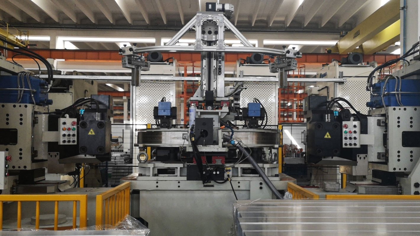
H Beam and I Beam Bending Machine
At present, the bending and forming of large steel sections, especially curved components such as I beams and H beams, is generally carried out using special pressure equipment and various rolling bending, pressure bending, tension bending, and forming orthopedic equipment.
Type 1#: Profile Bending Machine/Roll Bending H Beams and I Beams
When bending I beams and H beams using roll bending, one end of the steel I beams or H beams is first fed between the upper and lower rollers of the three-roll profile bending machine. Then, the left and right rollers move upwards, causing the steel beam between them to undergo a certain plastic bending deformation due to compression. When the upper roller makes a rotary motion, the meshing moment formed by the friction between the steel beam and the roller causes the steel beam to feed; when the steel beam passes between the upper and lower rollers (i.e., the deformation zone) in sequence, the steel beam obtains plastic bending deformation along its entire length.
The video on the left shows the PBC-360 profile bending machine bending IPE 200 I-beam with hard-way

PBC Profile Bending Machine have the ability to bend H-beam and I-beam the easy way (against the weak axis) and the hard way (against the strong axis). The tool components that PBC Profile Bending Machine use to bend wide flange and I-beam are a web stretcher.
These tools are critical to use when bending the hard way as they keep the critical web from buckling or distorting.
Roll bending I-beams or H-beams of the Hard Way
Bending an I-beam or wide flange beam the hard way (against its strong axis) involves significant challenges due to the high resistance to bending in this orientation. The web stretcher is particularly vital in this scenario because:
Web Buckling: Without support, the web can easily buckle under compression, leading to structural weaknesses.
Distortion: Bending forces can distort the web, causing it to deform in undesirable ways, which compromises the beam’s structural integrity.
For more on excellent profile bending machines, see Advantages of PBC Section Bending Machine.
Type 2#: Stretch Forming Machine/Stretch Bending H Beams and I Beams
Stretch bending/stretch forming, like roll bending, is a commonly used cold bending process for metal profiles in 2D or 3D spaces, offering the following advantages:
- Formation is stable, ensuring good accuracy and repeatability due to the absence of springback and residual stress
- Capable of forming complex shapes
- Reduces assembly operations
- Parts do not deform after welding or machining
- Wide range of applications
Like roll bending I-beams, stretch bending also faces the issue of web deformation during hardway bending. Therefore, it similarly requires additional tools to address this problem, typically using polymer filler strips to prevent deformation, as shown in the video on the right:
With unique springback control technology: PBF-C stretch forming machine
Type 3#: Cambering Machine
The Cambering Machine and Stretch Forming Machine belong to the same type of cold bending processing equipment/profile bending machine, utilizing full hydraulic control for easy operation and high production efficiency. It can cold bend large I-beams, round pipes, square tubing, and other profiles with a section below 1000mm. The resulting curves are perfect, with high precision, good stability, and no deformation.
Accurate, time-saving and low cost: Cold Cambering Machines: Incremental Cold Bending Profiles
Type 4#: Induction Bending Machine
Using a medium frequency power source to heat the I-beam while uniformly advancing it, the heated portion of the I-beam follows a preset track, thereby forming a certain curvature radius and angle. During bending, the I-beam is pushed forward by a cart powered by hydraulics, deforming and bending along the adjusted bending radius at the heating point. After the I-beam deforms, it is cooled by spraying water on it, thus obtaining the desired workpiece.
Remember that it can bend small diameters, which is irreplaceable by cold bending: Induction Bending Machine

Hello. What is the bending section modulus of I-beam?
The bending section modulus of a bent component is defined as the moment of inertia of the cross-section about its neutral axis divided by the distance from the neutral axis to the outermost edge of the section. The section modulus W.
W is the ratio of the moment of inertia about the centroidal axis of the section to the distance from the furthest point on the section to the centroidal axis. The section modulus, also known as the section resistance modulus, is used to calculate the normal stress in a section subjected to bending. In practical applications, the most common bending problem is transverse bending, where the cross-section experiences both normal stress and shear stress.
Formula for Section Modulus of I-Beam
I-beam bending section coefficient formula
The bending section coefficient is also called the bending section modulus, and it can also be called the bending resistance moment, represented by Wx and Wy.
Assume that the section height of the I-beam is h, the flange width is b, and the moments of inertia are Ix and Iy. Wx and Wy can be calculated according to the following formula:
Wx=2Ix/h
Wy=2Iy/b
Section modulus is the moment of inertia of the area of the cross section of a structural member divided by the distance from the neutral axis to the farthest point of the section; a measure of the flexural strength of the beam.
Section Modulus Formula
Area moment of inertia Ixx = H3b/12 + 2[h3B/12 + hB(H+h)2/4]
Area moment of inertia Iyy = b3H/12 + 2(B3h/12)
Section modulus Sxx = 2Ixx/(H + 2h)
Section modulus Syy = 2Iyy/B
Comments are closed.