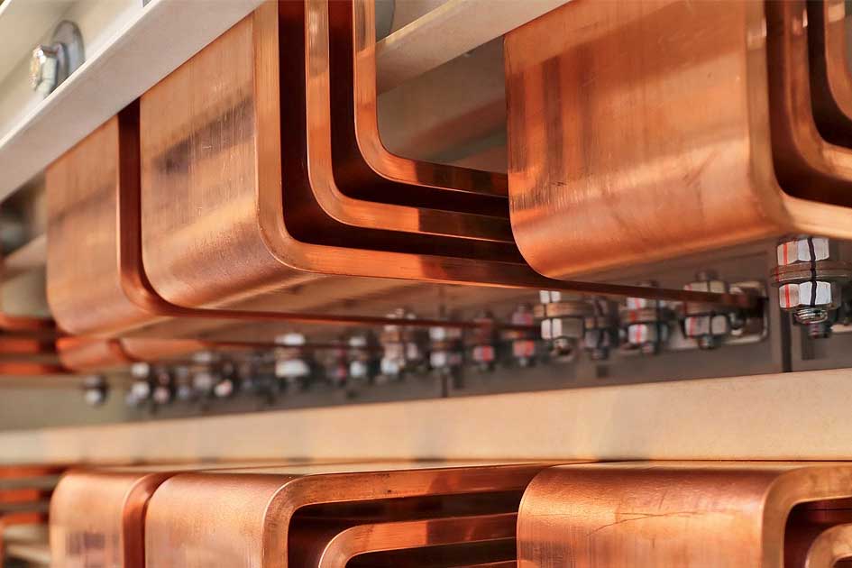
In electrical switchgear and distribution cabinets, copper busbars are generally installed in two ways: flat and vertical. Vertical installation provides slightly higher current-carrying capacity, which is why main busbars are usually mounted vertically.
The current-carrying capacity of copper bars and wires also varies with ambient temperature. The standard reference temperature is 35°C, and correction factors must be applied for other temperatures—higher temperatures reduce the allowable current.
Based on practical experience, the following rules can be used:
- Single busbar current capacity = Width (mm) × Thickness Coefficient
- Double busbar current capacity = Width (mm) × Thickness Coefficient × 1.5 (empirical factor)
- Copper and aluminum bars can also be estimated based on cross-sectional area: typically, copper carries 5–8 A per mm², while aluminum carries 3–5 A per mm²
Busbar Current Carrying & Bending Length Calculator
This calculator helps you estimate the current carrying capacity of copper busbars (with temperature compensation) and calculate bending lengths for both inner and outer bends. Based on practical formulas used in switchgear and power distribution systems.
Current Carrying Capacity Calculator
Formula: Single Layer = Width × (Thickness + 8)
For double layer: × 1.58, triple layer: × 2, four layer: × 2.45
Busbar Bending Length Calculator
Choose bending type:
Total Length: — mm

(Example diagram of busbar bending)
Busbar Bending Formula
The bending formula for a busbar depends on the material properties, the dimensions of the busbar, and the degree of bending required. Generally, the bending formula for a busbar can be expressed as follows:
R = K x t
where R is the minimum bending radius, t is the thickness of the busbar, and K is the bending coefficient.
The bending coefficient (K) is dependent on the material properties of the busbar and is typically determined experimentally. The bending coefficient can be expressed as a function of the yield strength (σy) of the material and the modulus of elasticity (E) of the material:
K = (σy / E) x (t / w)^(1/2)
where w is the width of the busbar.
The minimum bending radius ® can be calculated using the bending coefficient (K) and the thickness (t) of the busbar:
R = K x t
It is important to note that the minimum bending radius ® should be greater than or equal to the recommended bending radius specified by the busbar manufacturer to prevent damage to the busbar during the bending process.
Busbar Size Calculation Formula: Aluminium and Copper Examples
The size of a busbar is typically determined by its current carrying capacity and the allowable temperature rise. The following formulas can be used to calculate the size of a busbar:
Copper Busbars
Cross-sectional area of busbar (mm²) = (I x L x K) / (δ x ΔT)
where,
I = Current (in Amperes)
L = Length of busbar (in meters)
K = Factor for resistivity (typically 1.2 for copper)
δ = Density of copper (8.89 g/cm³)
ΔT = Maximum allowable temperature rise (in °C)
Aluminium Busbars
Cross-sectional area of busbar (mm²) = (I x L x K) / (δ x ΔT)
where,
I = Current (in Amperes)
L = Length of busbar (in meters)
K = Factor for resistivity (typically 1.6 for aluminum)
δ = Density of aluminum (2.7 g/cm³)
ΔT = Maximum allowable temperature rise (in °C)
Also see Aluminum Bending Machine with One-Key Compensation for Bending Springback
Case
Once the cross-sectional area of the busbar is calculated, the physical dimensions of the busbar (width and thickness) can be determined based on the standard sizes available from busbar manufacturers.
For example, let’s assume we need to calculate the size of a copper busbar to carry a current of 500 amps for a length of 3 meters with a maximum allowable temperature rise of 50°C.
Cross-sectional area of busbar = (500 x 3 x 1.2) / (8.89 x 50) = 10.15 mm²
Based on the standard sizes available from busbar manufacturers, we can choose a busbar with a cross-sectional area of 10.16 mm², which corresponds to a width of 25 mm and a thickness of 4 mm.
Similarly, if we need to calculate the size of an aluminum busbar to carry the same current and length with a maximum allowable temperature rise of 50°C, the formula and calculations would be the same, but with a different resistivity factor and density value.