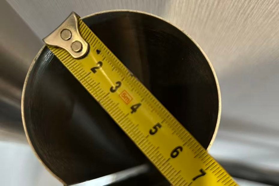
Explore how top-roll diameter, polyurethane deformation, and contact-point control influence radius accuracy and repeatability in two-roll plate rolling.
In the design of a two-roll plate rolling machine, multi-radius production raises a question that deserves more attention than it often receives: How should the machine produce different bending radii, and when interchangeable top rolls are used, how can the machine maintain consistent forming conditions after each roll change?
These are not simply questions of roll positioning. They involve several interacting mechanical factors, including top-roll geometry, polyurethane deformation, contact pressure between the rolls, and material springback after forming. More importantly, changing the diameter of the top roll and changing the compression of the polyurethane roll may both affect the forming process, but they serve fundamentally different purposes.
Understanding that distinction is essential when designing a two-roll machine capable of producing multiple radii with consistent results.
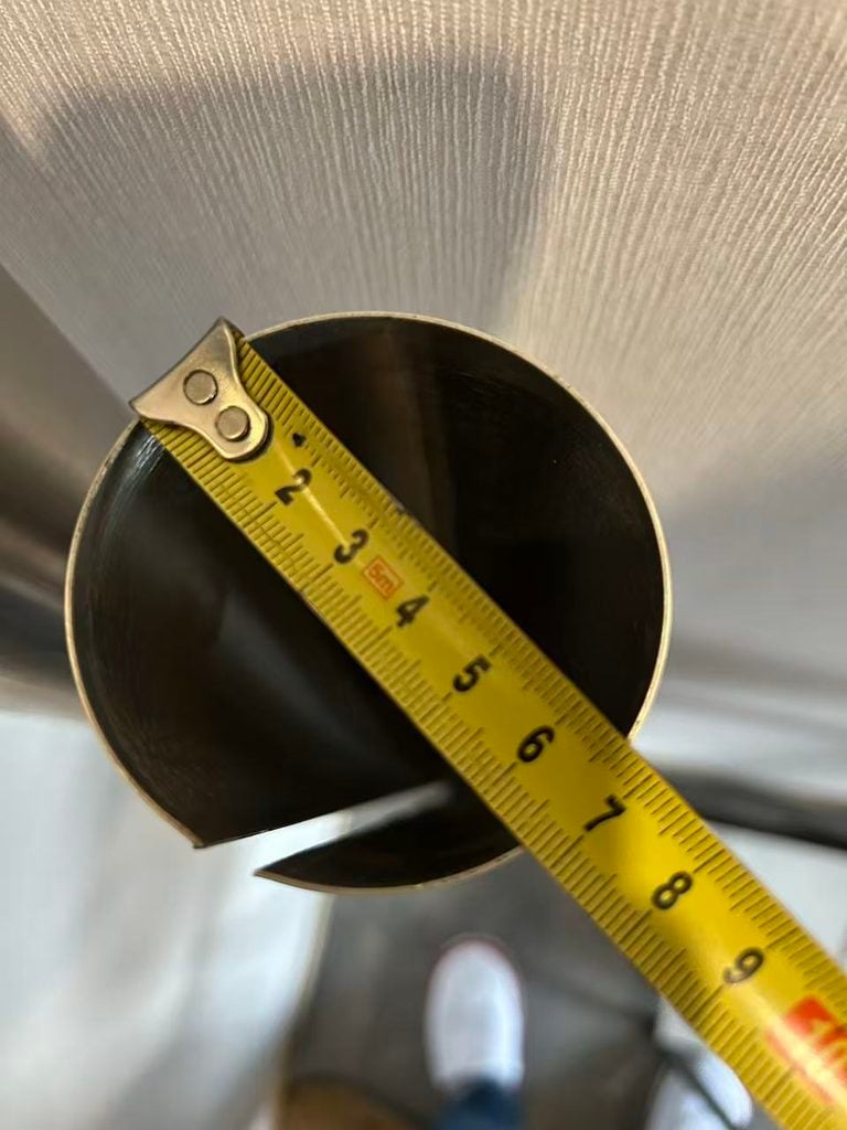
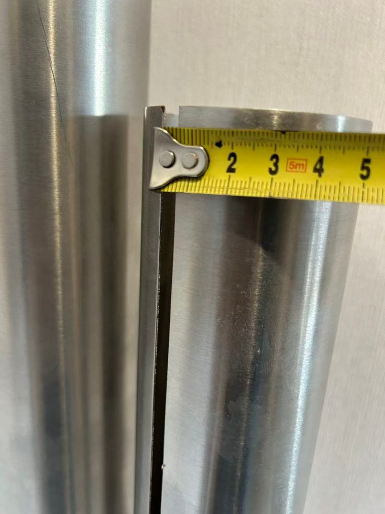
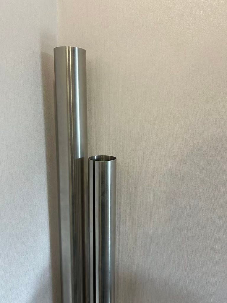
Why Different Bending Radii Require Different Top Rolls
A conventional two-roll plate rolling machine typically uses a rigid steel top roll and an elastomeric polyurethane-covered bottom roll. Unlike a conventional three-roll machine, which controls sheet curvature through changes in the relative positions of several rigid rolls, the two-roll system uses the elastic deformation of polyurethane to press the sheet tightly against the steel top roll.
In this arrangement, the top roll is more than a component that transfers rotational motion. Its outside diameter is a primary geometric factor in determining the curvature imposed on the workpiece.
As the sheet enters the space between the two rolls, the steel top roll penetrates the polyurethane-covered bottom roll, causing the polyurethane to deform. The resulting pressure forces the sheet against the cylindrical surface of the steel roll. As the rolls rotate, the sheet progressively conforms to the top roll’s geometry and undergoes continuous bending.
This explains why changing the relative position of the two rolls cannot simply replace changing the diameter of the top roll.
Adjusting the distance between the rolls primarily changes the compression of the polyurethane, the resulting contact pressure, and the conditions under which the sheet conforms to the steel roll. It changes the operating condition of the elastic forming zone, but it does not change the geometry of the steel roll itself. No matter how much the polyurethane is compressed, the outside radius of the steel top roll remains unchanged.
Consider a machine equipped with a relatively large-diameter top roll for producing large-radius components. If the production requirement changes to a substantially smaller radius, simply increasing the compression of the polyurethane while retaining the same top roll does not fundamentally change the forming geometry. It changes the polyurethane’s working condition instead. This may substantially alter the contact pressure, the deformation range, and the load distribution within the elastic roll, without reliably producing the required smaller radius.
For a two-roll machine designed around a fixed-diameter steel top roll and a polyurethane-covered bottom roll, using interchangeable top rolls of different diameters is therefore a direct and practical way to expand its forming range. The machine can be configured with different top rolls to accommodate different basic forming radii without redesigning the entire forming mechanism for every part requirement.
Of course, the top-roll diameter is not necessarily equal to the final inside or outside radius of the finished workpiece. Sheet thickness, material properties, plastic deformation, and springback after unloading all influence the final dimensions. The top roll establishes the basic forming geometry, while material springback determines how far the released workpiece deviates from that geometry.
This leads to the next engineering question: once a different top roll has been installed, can the machine reliably establish the same working conditions every time?
The Top Roll Determines the Basic Forming Geometry; the Polyurethane Roll Establishes the Contact Conditions
Acrotech provides a particularly clear explanation of the two-roll principle in its technical publication, The Art of Roll Bending.
The machine described uses a steel top roll and a polyurethane bottom roll. During operation, a portion of the steel top roll is pushed into the polyurethane roll, causing the polyurethane to deform. Acrotech compares this process to hydroforming: the displaced polyurethane generates substantial pressure against the steel roll and presses the incoming sheet tightly against its surface. As the polyurethane roll rotates, the sheet is progressively roll-formed along the geometry of the steel top roll.
One statement in the publication is particularly important:
“The radius of the rolled part is controlled by the radius of the top roll and the natural spring-back of the material.”
This statement identifies two distinct factors. The top roll establishes the basic forming geometry, while the material’s natural springback influences the final radius after unloading. The polyurethane roll provides the elastic pressure needed to maintain reliable contact between the sheet and the steel top roll during forming.
The polyurethane roll, therefore, is not the primary element used to select the target bending radius. Its main function is to establish the pressure-transfer and contact conditions required for the steel top roll to perform the forming operation.
This distinction matters when designing a multi-radius machine. Treating polyurethane compression as a direct radius-selection parameter confuses two separate aspects of the process: roll geometry and the operating condition of the elastic material.
Acrotech also makes an interesting observation about production consistency. If parts with incorrect radii begin coming off the machine during a production run, the material quality should be checked rather than immediately assuming that the machine settings have changed. Variations in hardness, temper, and material thickness can alter natural springback. In other words, even when the machine consistently establishes the same forming conditions, the final workpiece radius remains dependent on the material itself.
Reference: Acrotech, The Art of Roll Bending, p. 18.
The Polyurethane Roll Does More Than Apply Pressure
It is easy to describe the polyurethane-covered bottom roll as an elastic pressure roll, but that description does not fully explain its role in the forming process.
When the steel top roll penetrates the polyurethane, the elastomer changes shape. Because the material is constrained by the roll structure and the surrounding material, deformation extends beyond the initial point of contact, creating an elastic working zone with a distributed pressure field. As the sheet enters this zone, the polyurethane presses it against the steel top roll, maintaining contact as the material moves through the machine.
From a forming perspective, polyurethane provides a pressure-transfer mechanism with the ability to accommodate elastic deformation. It can respond to variations in sheet thickness and local contact conditions while providing relatively continuous support and restraint.
This is one of the important differences between the two-roll polyurethane system and a forming arrangement based entirely on rigid rolls. In the latter, the working condition is largely determined by the mechanical gap between the rolls. In the two-roll system, the deformation characteristics of the polyurethane become an integral part of the forming process.
This principle is not limited to modern two-roll plate rolling machines. German patent DE1552017B2, which dates back to the 1960s, describes a two-roll bending machine using an elastically deformable polyurethane material in combination with rigid mechanical components. The patent explains that urethane rubber deforms to conform to the shape of the forming component and acts in a manner similar to a confined hydraulic fluid, distributing pressure in multiple directions.
The patent illustrates the long-standing engineering principle of using an elastic polyurethane material to accommodate deformation and transmit forming pressure. For machine designers, the more important lesson is that polyurethane deformation is not an incidental side effect. It is part of the machine’s operating principle.
This is also why removing and reinstalling the top roll requires more consideration than simply returning it to its previous mechanical position. The actual working condition between the steel top roll and the polyurethane-covered bottom roll must also be re-established.
After Changing the Top Roll, What Actually Needs to Be Re-established?
For a machine dedicated to producing one fixed radius, establishing the operating conditions is relatively straightforward. Once the top roll is installed, its working position can be determined from the machine geometry. Trial forming can then be used to compensate for material springback. As long as the mechanical structure and material conditions remain stable, the machine can continue producing parts using the established parameters.
A multi-radius machine presents a different situation. Whenever production requires a change in the basic forming radius, the operator may need to remove the existing top roll and install another one with a different diameter.
Although the roll journals, mounting interfaces, and locating surfaces can be manufactured to precise tolerances, small differences may still occur during actual assembly. Bearing clearances, the cleanliness of mounting surfaces, wear in locating components, and variations in the final installed position can all influence the assembled condition.
With conventional rigid-roll arrangements, these variations mainly affect the relative position or working gap between the rolls. In a two-roll machine, however, they also influence the deformation of the polyurethane.
Suppose the control system has stored the working position associated with a particular top roll. After removing and reinstalling that same roll, the control axis may return to exactly the same absolute coordinate. Yet this does not necessarily mean that the actual contact condition between the steel roll and the polyurethane roll is identical to the previous installation.
Even a small change in the installed position can shift the initial contact point and alter the actual penetration depth into the polyurethane. In a machine that relies on polyurethane deformation to establish forming pressure, such a difference may affect the conditions under which the sheet conforms to the steel roll.
In other words, the control system knows where the moving component is positioned, but it does not necessarily know what working condition the machine has actually established.
This suggests a different approach to machine control. Rather than relying exclusively on predefined absolute coordinates after every top-roll change, the system could first identify the actual contact position and use that position as a new reference for establishing the working condition.
Starting at the Contact Point: Establishing a Repeatable Polyurethane Wrap
Based on the preceding analysis, I propose a control concept for multi-radius two-roll plate rolling machines: after each top-roll change, the machine should identify the actual contact position between the steel top roll and the polyurethane-covered bottom roll before proceeding to its working condition.
The sequence is relatively straightforward.
First, the control system moves the top roll toward the polyurethane bottom roll. Before contact occurs, the moving component is essentially approaching its target without significant resistance from the polyurethane. When the two rolls begin to make contact, the system detects the change through hydraulic pressure, load response, or another suitable sensing method and records the corresponding mechanical position. This becomes the actual contact reference for the current top-roll installation.
The top roll then continues moving downward, penetrating the polyurethane further until the predefined working condition is reached.
An important distinction must be maintained here: the purpose is not to select the bending radius by changing polyurethane compression. The top-roll diameter has already established the basic forming geometry. The purpose of controlling the subsequent penetration is to ensure that the polyurethane establishes a consistent and repeatable working condition, allowing the sheet to conform to the steel top roll under more consistent conditions.
For machine design, it may be worth investigating the use of the maximum permitted working wrap as a control reference. However, this maximum must be defined through validation of the machine structure, polyurethane material, and long-term operating performance. It should represent the upper limit of the normal working range, not the physical compression limit of the polyurethane, and certainly not an overload condition.
If the control system can identify the actual contact point after every top-roll change and then establish the same predefined target wrap, some of the positioning errors introduced during roll removal and reinstallation may be compensated for automatically.
This approach differs fundamentally from relying only on a mechanical zero point or an absolute position command. Absolute-position control focuses on where the moving component is located. Contact-referenced control focuses on the actual condition from which the machine begins building its working pressure. For a two-roll system that relies on polyurethane deformation, the latter may provide a more meaningful reference for establishing consistent operating conditions.
Of course, identifying the contact point requires a reliable detection method. Hydraulic pressure changes, load sensors, or displacement measurements could be considered for determining when contact occurs. The subsequent penetration process requires another level of investigation: how should the target polyurethane wrap be defined, measured, and monitored?
One preliminary approach worth testing is to use the downward movement time after the contact point as an indirect control parameter. If hydraulic speed, polyurethane temperature, and material condition remain stable, a calibrated movement time may correspond to a reasonably repeatable penetration process.
However, time is not a direct measurement of compression, nor can it independently confirm that the actual polyurethane working condition is identical. Where machine configuration permits, it would be more reliable to combine displacement and pressure signals to monitor the process and evaluate the relationship between the two.
There is another factor that cannot be ignored. Polyurethane is a viscoelastic material. Its deformation response depends not only on temperature but also on loading speed, loading history, material hardness, and the effects of long-term fatigue and wear. Even under similar temperature conditions, its response may not be exactly the same every time.
For this reason, the control parameters should not be established solely through theoretical calculations. They need to be calibrated and validated through actual machine testing.
The Final Measure of Control Accuracy Is the Workpiece
The effectiveness of this control approach cannot be judged simply by whether a servo axis repeatedly reaches the same position or whether the hydraulic system produces the same displayed pressure.
The real question is whether the machine can consistently produce workpieces with the required bending radius after repeated top-roll removal and reinstallation, provided that the material, thickness, and processing conditions remain the same.
A practical evaluation can begin with a single top roll.
First, repeatedly remove and reinstall the same top roll. For each installation, produce identical test pieces using the existing fixed absolute-position control method and record the resulting workpiece radii.
Then repeat the same installation and forming procedure using contact-point identification and predefined polyurethane wrap control. Again, produce identical test pieces and measure their actual radii.
The two test groups should use the same material batch, sheet thickness, material orientation, polyurethane temperature, hydraulic conditions, and forming speed as far as possible. Multiple workpieces should be measured in each group to establish meaningful comparisons.
The results will show whether contact-point identification actually reduces the variation in workpiece radius caused by repeated top-roll installation. If the displayed penetration positions become more consistent but the final workpiece radii do not improve, the control method has not yet demonstrated its practical value.
If the method proves effective, it can be extended to different top-roll diameters. The machine could maintain a corresponding contact reference and polyurethane wrap parameter set for each top roll. These parameters could then be combined with material specifications, sheet thickness, and springback compensation data to create a multi-radius forming parameter system.
It is important to emphasize that consistent polyurethane wrap does not mean that different materials will produce exactly the same final radius. Yield characteristics, thickness, hardness, and springback will continue to influence the released workpiece dimensions.
Machine working-condition control and material springback compensation therefore need to be treated separately. The first addresses whether the machine can repeatedly establish the same forming conditions. The second addresses how much the material changes dimension after unloading.
From Geometric Positioning to Actual Working-Condition Control
Existing two-roll rolling technology clearly demonstrates the fundamental relationship between the steel top roll and the polyurethane-covered bottom roll. The top roll establishes the forming geometry, the polyurethane roll generates pressure through elastic deformation and provides the wrapping action, and material springback influences the final workpiece radius.
U.S. patent US20080098785A1 also discusses, in its background section, bending-roll arrangements using a steel upper roll and a polyurethane-covered lower roll. It describes how the forming process is influenced by the contact pressure and the diameter of the upper roll. Although the patent’s principal invention concerns a different forming arrangement, its discussion provides additional context for understanding the relationship between roll geometry and elastic contact pressure.
Reference: U.S. Patent US20080098785A1, Roll-forming or Bending Machine.
Building on these established mechanical principles, I am interested in a more specific machine-design problem: when a multi-radius two-roll plate rolling machine uses interchangeable top rolls, how can the machine reduce the influence of installation-position variations on the working condition of the polyurethane roll and consistently re-establish the required forming conditions?
Contact-point identification and polyurethane wrap control are a proposed approach to this problem. The concept does not attempt to redefine the basic forming principle of a two-roll machine. Instead, it seeks to bring the actual working condition of the polyurethane roll into the machine’s control system, allowing the machine to establish a new working reference based on the actual contact condition after each installation rather than relying exclusively on predefined mechanical coordinates.
Whether this approach can significantly improve workpiece radius repeatability remains a question for comparative testing. Nevertheless, it offers a worthwhile direction for further engineering development.
For machine designers, the important objective is not simply to make the control system repeat the same movement commands. It is to ensure that the machine re-establishes the same actual forming conditions every time a roll is installed, adjusted, or brought back into operation.


