Railway vehicles offer high carrying capacity and operational efficiency, making them one of the major modes of transportation. Because the structural components of railway vehicle bodies are large in size and require high dimensional precision, they are generally manufactured using stretch forming, particularly for forming aluminum extrusions. Stretch forming applies a tangential stretch force during bending, improving the stress state of the extrusion cross-section, reducing springback, and enhancing contour accuracy. High-precision forming of car-body components is therefore one of the key technologies in railway vehicle body manufacturing.
Numerical Simulation of Extrusion Stretch Forming for an Aluminum Extrusion End-Beam Component of a Rail Vehicle Body
In this study, an aluminum extrusion end-beam component of a railway vehicle body is selected as the research object. A numerical simulation model of extrusion stretch forming is established to investigate how various process parameters affect cross-sectional deformation and contour accuracy during stretch forming aluminum extrusions, and to optimize the stretch forming process for practical production.
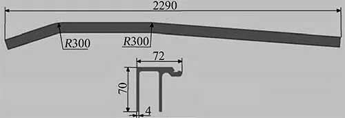
The geometric model of the end beam is shown in Figure 1. This component is produced by stretch forming aluminum extrusions. Based on the geometry, a finite-element model of the stretch forming process is constructed (Figure 2). The model consists of the extrusion profile, the clamps, and the forming die. The forming die and clamps are modeled as rigid bodies, while the aluminum extrusion is modeled as a deformable shell.
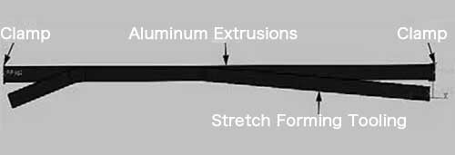
To improve computational efficiency, the clamps are simplified to planar surfaces, and the extrusion ends are connected to the clamps through a binding constraint. During extrusion stretch forming, the forming die remains stationary, while the translational and rotational motion of the clamps causes the aluminum extrusion to wrap around the die and bend into its final shape.
Analysis of Simulation Results
Study of Factors Influencing Cross-Sectional Deformation
For this car-body component, when the stretch strain is less than 8% of the extrusion length, the bent section shows minimal cross-sectional deformation.
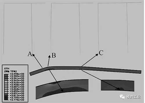
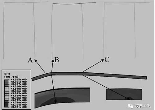
As illustrated in Figure 3(c), Region B—where the curvature is the greatest—exhibits significant web buckling and flange bending, resulting in pronounced cross-section distortion. Regions A and C, with smaller bending curvature, show notably less distortion.
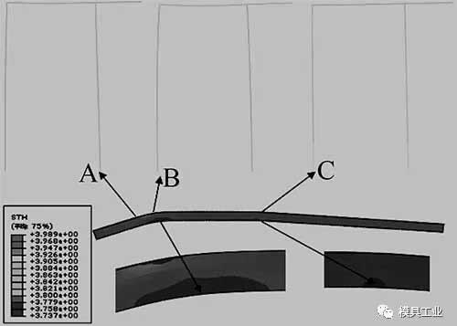
When the stretch strain is 6%–8% of the extrusion length, all three regions (A, B, C) exhibit good cross-section integrity with no significant distortion.
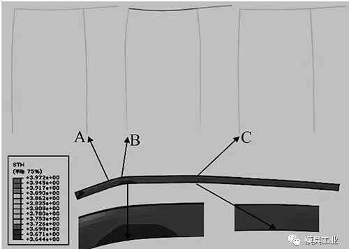
At 10% stretch strain, Region B displays severe web collapse and flange bending, while Regions A and C remain relatively unaffected.
At 12% stretch strain, cross-section distortion becomes more severe in Region B, and noticeable flange bending appears in Regions A and C as well.
Thus, cross-section distortion increases progressively with higher stretch strain.
Overall, when the stretch strain is below 8% of the extrusion length, cross-section deformation remains acceptable.
Study of Factors Affecting Contour Accuracy
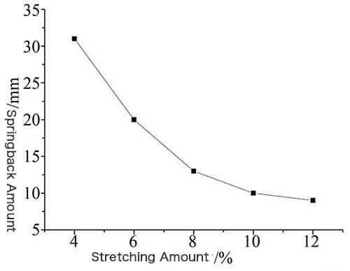
The springback-versus-stretch-strain curve during extrusion stretch forming is shown in Figure 4. The stretch strain applied during forming aluminum extrusions has the greatest influence on springback. Within a certain range, increasing the stretch strain reduces springback and thus improves contour accuracy.
However, the influence of stretch strain on springback is limited, and excessive strain can lead to cross-section distortion. To control contour accuracy, the forming die surface can be corrected based on the calculated springback. In the initial model, the outer surface of the forming die is generated by offsetting the theoretical outer contour of the part by the material thickness. The gap between the formed part and the theoretical contour represents the springback amount. Based on the contour gap at different positions, reverse compensation is applied locally to the forming-die curve. Stretch forming is then simulated using the corrected die surface to determine the optimal compensation factor.
Compared with the theoretical part, the springbacked component exhibits changes in dimensions and bending angle, which are collectively manifested in the overall contour deviation. Therefore, die-surface compensation based on the contour gap inherently accounts for both dimensional and angular changes.
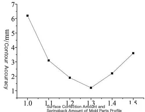
When the stretch strain is 8% of the extrusion length, the relationship between contour accuracy and die-surface compensation is shown in Figure 5. The results indicate that when the compensation factor is 1.3 times the springback amount, contour accuracy is significantly improved, meeting service requirements.
Stretch Forming Experiments
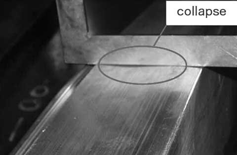
As shown in Figure 6, excessive stretch strain reduces springback but may also cause severe cross-section distortion such as web collapse.
Considering all factors, the optimal stretch strain for this aluminum extrusion end-beam component is determined to be 8% of the extrusion length.

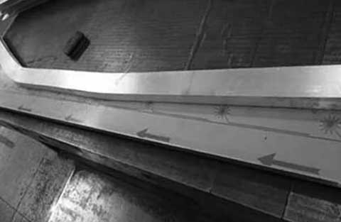
Based on this stretch strain, stretch forming experiments were conducted on a PBF-C CNC stretch forming machine (Figure 7). After correcting the forming-die surface, qualified bent components were successfully produced (Figure 8). The aluminum extrusion end-beam component has now been successfully applied in aluminum car bodies for rail vehicles.
Conclusion
- During stretch forming aluminum extrusions, the end-beam component is prone to cross-section distortion such as web collapse and flange bending, especially in regions with high curvature.
- Cross-section distortion becomes more severe with increasing stretch strain. When the stretch strain is below 8% of the extrusion length, the cross-section remains well-formed.
- Increasing stretch strain can reduce springback and improve contour accuracy, but excessive strain induces distortion.
- Die-surface compensation based on springback effectively enhances contour accuracy. For this component, the optimal compensation amount is 1.3 times the springback when the stretch strain is 8%.